Hi,
I am trying to recreate Casio VL-1 clone with Cabbage. I stuck right on beginning - on generating waveforms.
These waveforms are pretty simple actually, you can almost draw them on the graph paper. I am pretty convinced it’s possible to generate them with GEN02 and then play it with poscil3. However I am struggling how to transcribe them.
There is a both description and graph of these waveforms at https://syntherjack.net/casio-vl-1-secrets/
Can you provide example how to implement them (7 - Electro sound 1 looks like good example) or example of other transcribed waveform with graph representation?
Are they the waveforms down the bottom of that page? They all look like square waves with varying duty cycles. You should be able to recreate them using a vco2, with its mode set to 2 (square wave with PWM). Let me know how you get on. If you have a short audio sample from any of the sounds it might make things easier 
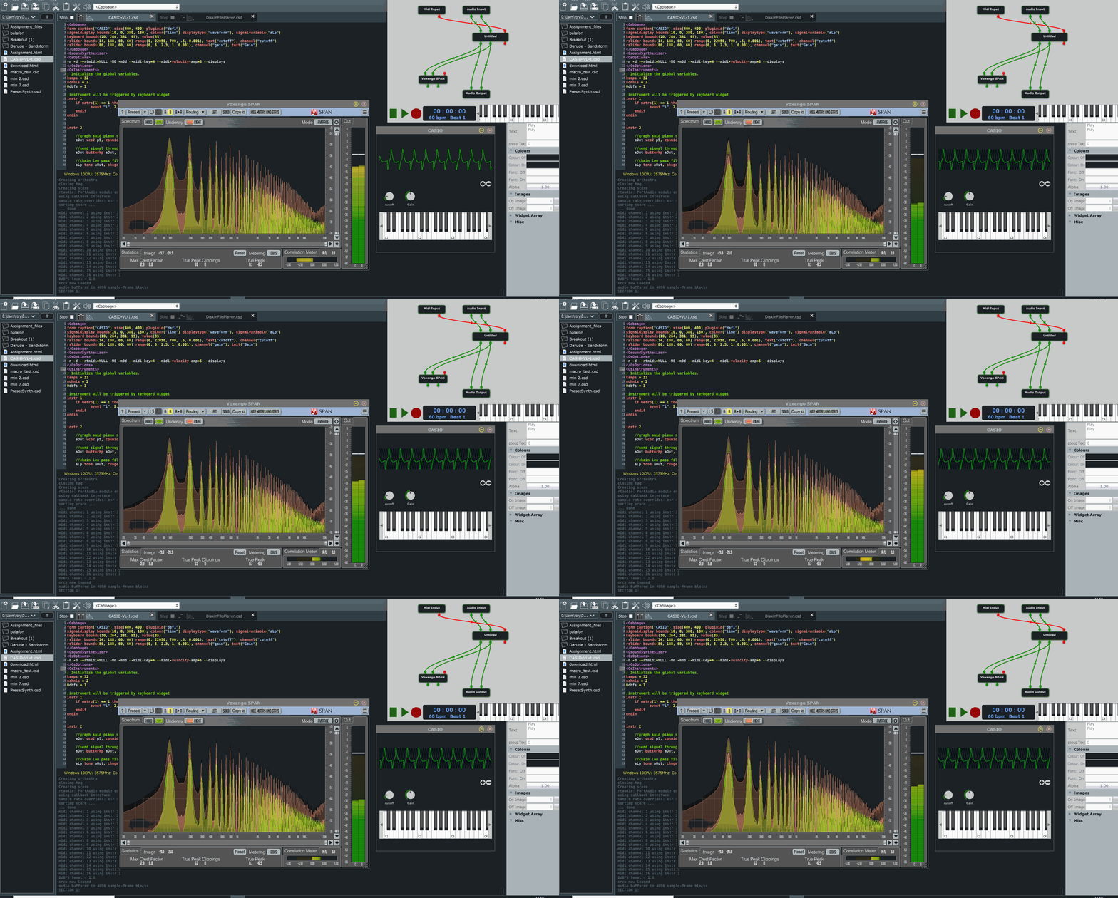
I managed to find some samples, although I’m not sure how good they are. Anyhow, I created a simple instrument that will play back the recorded sample, along side the synthesised sound so I could compare them. The synth sounds goes out the left channel while the sample is fed out the right. The code looks like this:
instr 2
    //graph said piano sound was with 70% PWM
    aOut vco2 p5, cpsmidinn(p4), 2, .7
    //send signal through high-pass filter
    aOut butterhp aOut, 60
    //chain low pass filters for more slope
    aLp tone aOut, chnget:i("cutoff")
    aLp tone aOut, chnget:i("cutoff")
    //play original samples
    a1, a2 diskin2 "122673__acollier123__piano-g-low-short.wav", 1, 0, 0
    //create env follower for original sample
    aEnv follow a1, .01
    //output needs some scaling
    outs aLp*aEnv*chnget:k("gain"), a1
    //display waveform
    display	aLp, .1, 2
endin
The code is pretty simple as you can see. The first thing I do is create a square wave with a 70% duty cycle, as per the site you linked. I then send it through a high-pass filter as the sample I’m working with has no energy below 60/70Hz. I then chain the signal through 2 low pass filters. You can try with just one, but two gives a better roll-off. The the sample is loaded from disk. As I don’t want to bother working out the ADSR elements right now, I use the follow opcode to generate a simple envelope from the sample. I then apply a bit of amplitude scaling before outputting and displaying the waveform.

In the Cabbage patcher I load Voxengo’s free SPAN FFT plugin. This gives me a nice way of viewing the similarities between the left and right channels. As you can see, it’s not perfect, but for 10 minutes of work it’s not that bad.
I’m not sure how much success one might have modelling this, without actually having access to the device. Here’s the full instrument code.
CASIO-VL-1.csd (1.5 KB)
Thanks for looking into it. I have no access to original hardware, but there are some emulators. One of them - Polyvalens VL-1 even have source code available and I looked into it.
I decided to implement those simple waveforms with vco2 and complex waveforms (violin and guitars) using GEN02 ftables. It works somehow, but I am unable to switch ftables (because this is defined in i-rate variable and I don’t know how to reinit instrument). See my code here - https://tildegit.org/severak/falco/src/branch/master/cabbages/dentaku.csd
Also - those GEN02 tables are constructed in my helper table (from waveforms on picture linked before) and then transfered by copy-paste-fu to CSD file. It’s tedious but works.
Thanks for the link. I haven’t tried it, but I also took a look through the sourcecode. It seems pretty simple. One first look it appears that his brute force method of creating the waveforms will cause all sorts of aliasing, but I see reference to an oversampling variable that he might be using to prevent aliasing. I’d need to look more into the code.
If you won’t be swapping tables during a note just use an i-rate chnget.
Works like magic. These k-rates and i-rates are pretty confusing.
I know. I have to constantly remind my students of the differences 


